Introduction
A joystick is made up by a couple of potentiometers and a switch button.
You just need a bit of knowledge about analog and digital input to get it work with almost any kind of board.
It is very easy to connect:
GNDto GROUND+5Vto a5Vvoltage sourceVRxanalog value ofxcoordinateVRyanalog value ofycoordinateSWdigital value of joystick pressure
Arduino
As you learned from Potentiometer blog post, a potentiometer is a knob that provides a variable resistance. Joystick’s position over cartesian axes provide a couple of analog input values to the Arduino board.
Arduino uses analogRead() function to read the value from the given analog pin (A0, A1, and so on).
It contains a multichannel, 10-bit analog to digital converter.
It will map input voltages between 0 and the operating voltage (5V or 3.3V) into integer values between 0 and 1023.
There are 210 = 1024 different values.
Common hardware setup
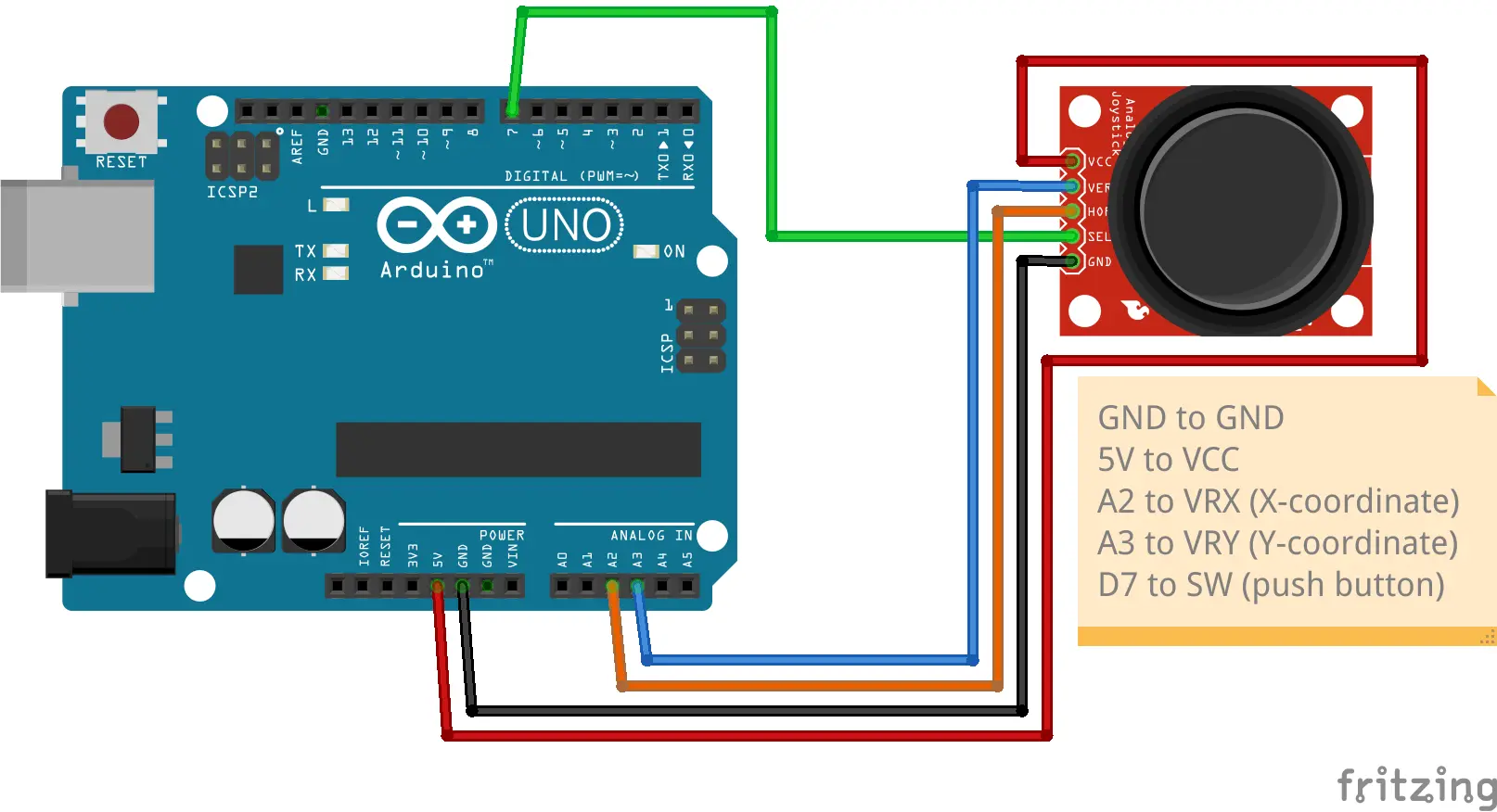
The above diagram shows how to connect the joystick to an Arduino Uno.
You can use any digital pin for SW and any couple of analog pins for VRx and VRy.
Position VS Values
joystick-values.ino sketch takes SW, VRx and VRy values and print them on the serial monitor.
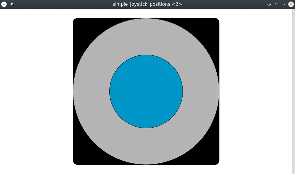
Coordinate values (x, y) = (510, 510) means that the joystick is not moving in any direction.
The more you move the joystick up, the more y coordinate decrease.
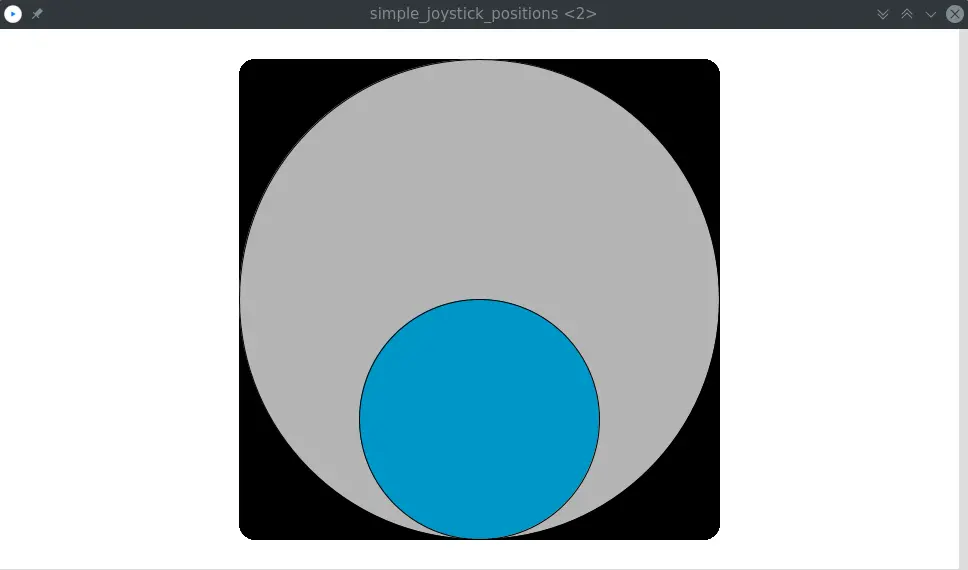
The more you move the joystick down, the more y coordinate increase.
The more you move the joystick left, the more x coordinate decrease.
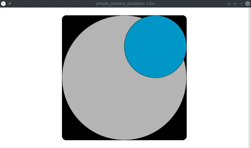
The more you move the joystick right, the more x coordinate increase.
This couple of analog values could be difficult to manage since you have to deal with two different coordinates.
Moreover, very often, you don’t really need to know the exact value of x and y, but you only care about its position (up, down, left, right, diagonals, …).
joystick-positions.ino sketch “translate” the coordinates’ values into an integer value that correspond to the position of the joystick.
To do so, it implements this self-explanatory enumerator:
enum position {
  NONE,        // x =  510 ; y =  510
  UP,          // x =  510 ; y =    0
  DOWN,        // x =  510 ; y = 1023
  LEFT,        // x =    0 ; y =  510
  RIGHT,       // x = 1023 ; y =  510
  UP_RIGHT,    // x = 1023 ; y =    0
  UP_LEFT,     // x =    0 ; y =    0
  DOWN_RIGHT,  // x = 1023 ; y = 1023
  DOWN_LEFT,   // x =    0 ; y = 1023
};
It uses a couple of integer thresholds to approximate directions. Even if the joystick is not fully positioned in a given direction, the code will send that direction.
#define MIN_THRESHOLD 400
#define MAX_THRESHOLD 800

enum axis_approximation {
  MIDDLE, // MIN_THRESHOLD <= value <= MAX_THRESHOLD
  MIN,    // value < MIN_THRESHOLD
  MAX,    // MAX_THRESHOLD > value
};
This means that, for example, UP direction will be sent if:
xaxis betweenMIN_THRESHOLDandMAX_VALUE(from0to400)yaxis minor thanMIN_THRESHOLD(from400to800)
Processing integration
Processing is a flexible software sketchbook and a programming language for learning how to code within the context of the visual arts. It’s used by thousands of visual designers, artists and architects.
Museums such as the Exploratorium in San Francisco use it to develop their exhibitions. It is also used in classrooms worldwide: art schools, visual arts programs in universities, computer science programs and many more.
The most important thing about Processing and culture is how the software has engaged a new generation of visual artists to consider programming as an essential part of their creative practice.
The Processing approach has also been applied to electronics through the use of Arduino.
Processing has different modes (dialects) according to the language on which it is based:
- Java: Processing (standard mode)
- JavaScript: p5js
- Python: Processing.py
- Android OS: Processing for Android
Users can also create their own mode for the language they prefer.
Having said that, you can integrate Processing with Arduino by establish a serial communication.
// simple_joystick_positions.pde

// import the Serial library
import processing.serial.*;

// the number 10 is ASCII for linefeed: end of Serial.println()
int end = 10;
String serial;
Serial port;

void setup() {
  fullScreen();

  println("Arduino connected to port " + Serial.list()[0]);

  // initializing the object by assigning a port and baud rate
  // must match that of Arduino
  port = new Serial(this, Serial.list()[0], 9600);

  // throws out the first reading, in case we started
  // reading in the middle of a string from Arduino
  port.clear();
  serial = port.readStringUntil(end);
  serial = null;
}

// draw() function is Arduino's loop() function
void draw() {
  // as long as there is data coming from serial port, read it and store it

  while (port.available() > 0) {
    serial = port.readStringUntil(end);
  }

  if (serial != null) {
    int pos = int(float(serial));
    println("position: " + pos);

    // place your code here
  }
}
You only need to connect the Arduino board to the computer through the serial port and run the Processing sketches I will provide you.
However, sketches about joystick integration are available at processing/ subdirectory of joystick-positions.
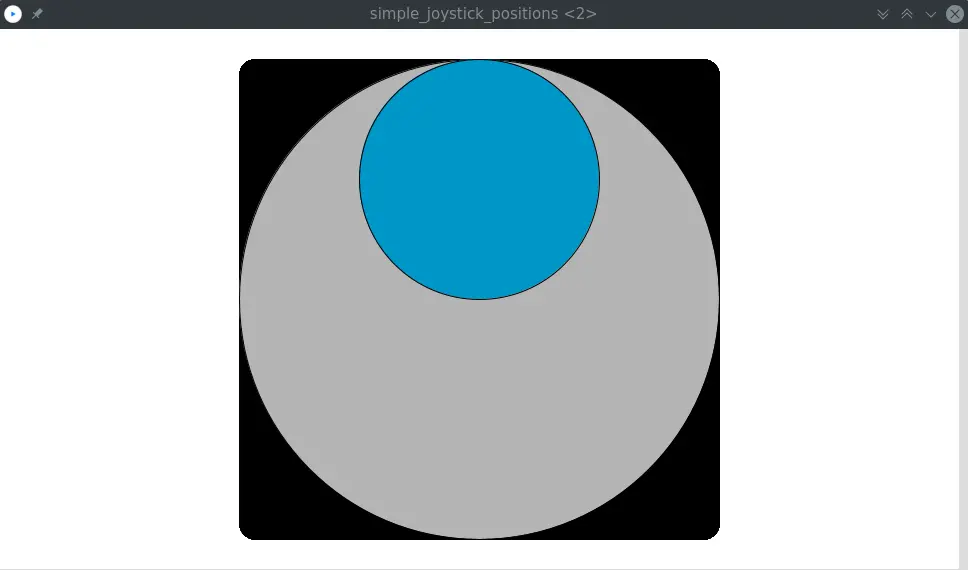
Simple Joystick Positions
To run this sample sketch I made, you first need to download Processing IDE.
Upload joystick-positions.ino sketch on your Arduino board.
Open simple_joystick_positions.pde sketch on Processing IDE and click on the Run button.
Below are shown some screenshots about its execution:
Conclusion
Documentation
All the sketches used in this post are available at joystick directory of arduino-projects GitLab repository.
Useful links:
- joystick on AliExpress
- speechtexter.com helps me to write this article
- Processing
- p5js
- instructables.com